|
||||||||||||||||||||||||||||||||||||||||||||||||||||||||||||||||||||||||
| ND = low pressure side, HD = high pressure side | ||||||||||||||||||||||||||||||||||||||||||||||||||||||||||||||||||||||||
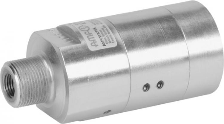
| Design: Steel housing galvanized and chrome plated, piston and valve seat from steel. Oil supply via threaded port. |
||||||||||||||||||||||||||||||||||||||||||||||||||||||||||||||||||||||||
| Application: Hydraulic intensifier are used to pressurise hydraulic clamping fixtures and assembly devices. The low pressure of the tooling machine's hydraulic system will be converted into a higher operating pressure according to the ratio. Input pressure and output pressure are proportional. The output pressure can be adjusted by the input pressure. |
||||||||||||||||||||||||||||||||||||||||||||||||||||||||||||||||||||||||
| Features: The most important functions are shown in the hydraulic circuit diagram. Oil is guided through directional valve CV to input IN and flows unimpeded through check valves KV1, KV2 and DV and into high pressure area H. In these conditions the pressure intensifier achieves a maximum flow rate with rapid forwards motion. Once input pressure IN is achieved in high-pressure area H, valves KV1, KV2 and DV close. The output pressure is built up by oscillating pump unit OP. The unit switches itself off automatically when the output pressure is achieved in high-pressure area H. In case of pressure loss in the high-pressure area due to consumption or loss of oil, pump unit OP starts automatically in order to maintain the output pressure. Pressure can be relieved from the high pressure area via the directly controlled valve DV. |
||||||||||||||||||||||||||||||||||||||||||||||||||||||||||||||||||||||||
| Note: The hydraulic oil must be filtered with mesh size not larger than nominally 10 µm, 19/16 according ISO 4406. If the intensifier will be used for applications where the oil supply is disengaged, a leakage free pilot controlled check valve should be installed between high pressure output H and the cylinder. Please consider the min. control pressure for releasing. The design of the intensifier allows a certain leakage between the ports IN and R. This has to be considered in uncoupled operations. |
||||||||||||||||||||||||||||||||||||||||||||||||||||||||||||||||||||||||
| On request: Manifold mounting and other sizes available on request. |
||||||||||||||||||||||||||||||||||||||||||||||||||||||||||||||||||||||||
MIỄN PHÍ GIAO HÀNG
ĐƠN HÀNG TỪ 5.000.000Đ TRỞ LÊN