|
||||||||||||||||||||||||||||||||||||||||||||||||||||||||||||||||||||||||||||||||||||||||||
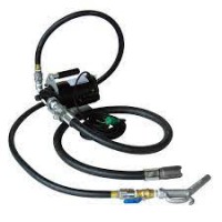
| Design: Steel housing galvanized and chrome plated, piston and valve seat from steel. Oil supply via oil channel in fixture body. |
||||||||||||||||||||||||||||||||||||||||||||||||||||||||||||||||||||||||||||||||||||||||||
| Application: Hydraulic pressure boosters are used in clamping fixtures and assembly fixtures. The low pressure of the tooling machine’s hydraulic system is converted into a higher operating pressure according to the transmission ratio. Input pressure and output pressure are proportional. The output pressure can be adjusted by the input pressure. |
||||||||||||||||||||||||||||||||||||||||||||||||||||||||||||||||||||||||||||||||||||||||||
| Features: The most important functions are shown in the hydraulic circuit diagram. Oil is routed via the directional control valve to the IN connection and then then flows unhindered through non-return valves KV1 and KV2, as well as through non-return valve DV in the high-pressure range A. Under these conditions, a maximum flow through the pressure booster is achieved and a fast forward movement is generated. If input pressure IN is reached in the high-pressure area, valves KV1, KV2 and PV close. The output pressure is built up by oscillating pump unit OP. The unit switches off automatically when the final pressure has been reached in the high-pressure area A. In case of a pressure drop in the high-pressure area due to oil consumption or oil loss, pump unit OP will start automatically in order to maintain the final pressure. The pressure in the high-pressure area can be relieved via the the directly actuated pressure valve. |
||||||||||||||||||||||||||||||||||||||||||||||||||||||||||||||||||||||||||||||||||||||||||
| Note: The hydraulic oil is to be filtered to a max. nominal filter mesh of 10 µm, max. 19/16 to ISO 4406. When installing in systems in which the supply is decoupled from the pressure booster, a leak oil-free, releasable non-return valve should be installed on the high-pressure side. It must be noted that the pilot ratio of the valve must be greater than the transmission ratio of the pressure booster. The structure of the pressure booster permits a certain leakage between the IN and R connections, which must be taken into account in decoupled installations. |
||||||||||||||||||||||||||||||||||||||||||||||||||||||||||||||||||||||||||||||||||||||||||
MIỄN PHÍ GIAO HÀNG
ĐƠN HÀNG TỪ 5.000.000Đ TRỞ LÊN